In my last post on materials, I explained what a material is, and the basic paraemeters that describe one. In this post, I’ll be demonstrating how to make your own materials in Unreal Engine!
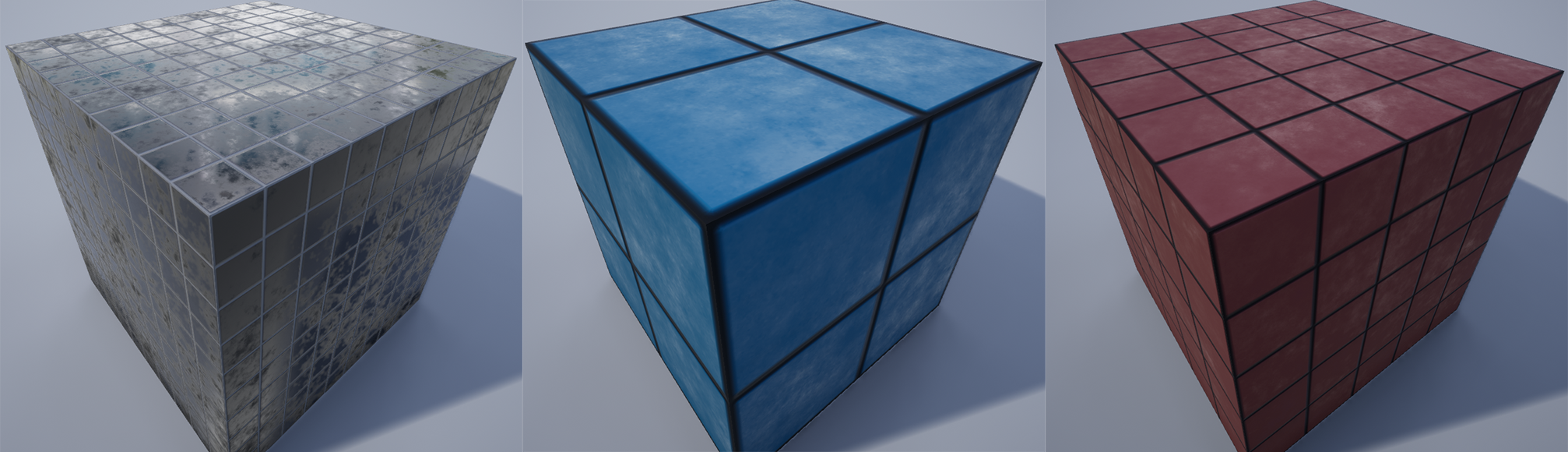
Here’s what we’ll be making:
Start by downloading and installing Unreal Engine. Create a new blank project.
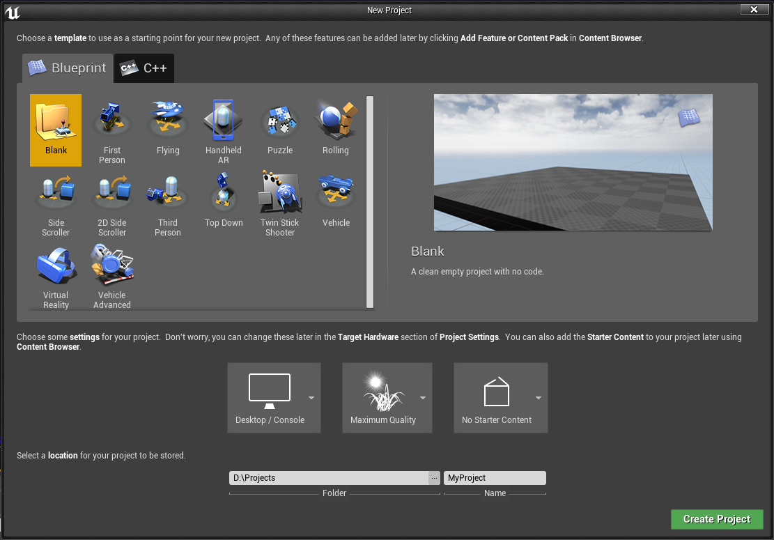
We don’t need the starter content, so don’t include it. Or do. I’m not your mom. But all of the content in Unreal Engine is already accessible from any project, so we won’t need to include the starter content here.
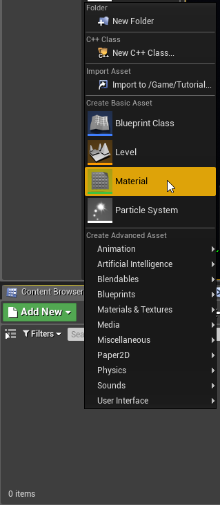
Once you’ve opened up your new project, right click inside the content browser panel at the bottom of the screen and select Create Basic Asset > Material.
Double-click on the new material to open the material editor.
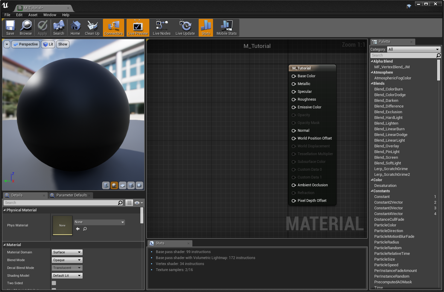
On the right side is a preview of the material applied to a sphere. Below it is the inspector, which shows the details of whatever node we have selected, or the options for the whole material if nothing is selected. In the center is the node editor, where we’ll be building the material. Finally, on the right is a searchable list of all available material nodes.
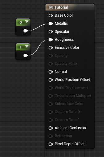
Right now, there’s only one node: the output node.
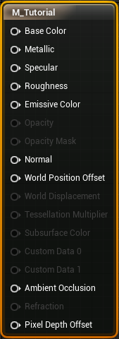
Each of these points is one property for the material. Some of these are greyed out, like opacity. That’s because they aren’t applicable to the current material. Remember in the last post, when I explained that materials are opaque by default? Since this is an opaque material, we don’t use the opacity property. You can still hook stuff up to it, it just won’t do anything. There are also a few properties I didn’t cover in the last post, but we won’t be using any of them in this tutorial. I’ll explain them in another article later.
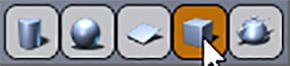
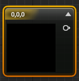
In the bottom-right corner of the preview pane, there are a few icons. These buttons change the preview model used to display the material. You can even supply your own model using the far-right button. Since we’re making a material for flat tiles, select the cube:
You can click and drag in the preview window to rotate the view, and use the scroll wheel to zoom.
Right-click anywhere inside the node editor to bring up this dropdown list:
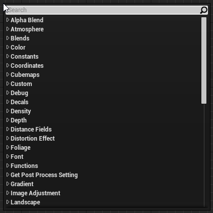
This is a list of available nodes, the same list that’s visible on the right side. You can just start typing to filter the list down, and hit enter or click on an item to add it. Alternatively, you can drag an item out of the list on the right side panel to add a node. From this point on in the tutorial, I’ll just say to “add X node”, and you can use either the right-click menu, or the panel on the right, whichever you prefer.
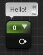
Start by adding a “Constant” node:

This is probably the simplest node. It reperesents a single value, which never changes (a “constant” value).
With the constant node selected, in the inspector on the right, we can see the properties for the node.
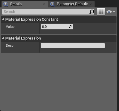
As expected, there’s just a single value for the node. There’s also a space where you can write a comment that will show up above the node:
Leave the value at 0 for now, and click and drag the output of the constant node, over to the input for “Roughness”, and release.
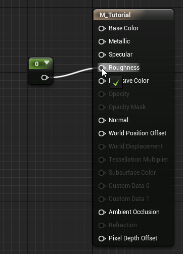
With these points hooked up, the value for Roughness is now set to the constant value 0 – it’s zero across the whole material. In the preview pane, the material will automatically update and become glossier, since we reduced the roughness to 0. Try changing the constant to 1 and see what happens!
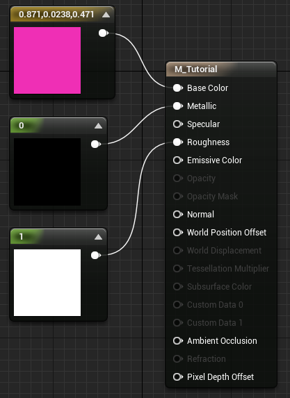
Add another constant for Metallic. There’s a shortcut for adding constants: hold the 1 key and click to add a constant node. Hook that constant up to the Metallic input. Your nodes should look like this now:
Wait, why was the shortcut for that to hold 1? Well, try holding 3 and clicking.
The answer is that the constant node is a single value, a one-dimensional vector, if you will. This new Constant3Vector node is a 3D vector – a fancy way of saying a group of 3 values. Since we’re making materials here, Unreal treats this Vector3 as a color – one value for red, one for green, and one for blue. (Computer screems make colors by combining red, green, and blue light in various amounts.)
Hook this node up to the Base Color node and play with the values in the inspector on the left. You can click on the colored bar to open a color picker. The material will change color to match, and the box on the node itself will show the color too. If desired, you can click the arrow in the upper right of the node to collapse it and hide the preview. You can also expand the single constant nodes, although it’s not a very useful preview since it’s just a single value. Most nodes have an optional preview like this.
If you set any of these values to outside of the 0..1 range, they’ll be clamped inside that range. (Well, most of them will. Emmisive, for example, is unclamped, and you can even allow special behavior for negative values.) This is true for the final output nodes, but not the intermediary nodes. The ability to have values outside of 0..1 for calculations inside the material is very important.
Let’s add a texture map. Here’s a tile mask and normal map you can use:
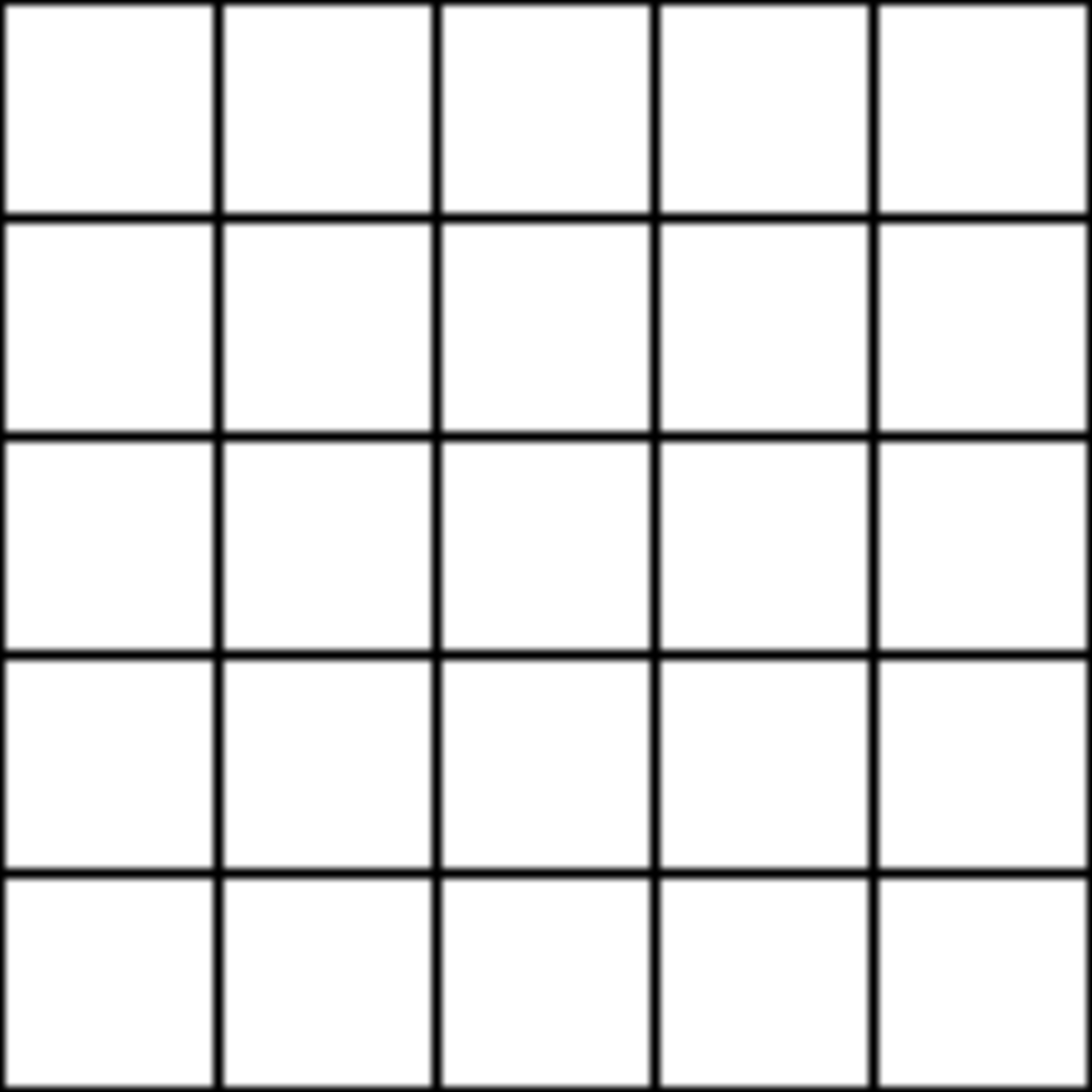
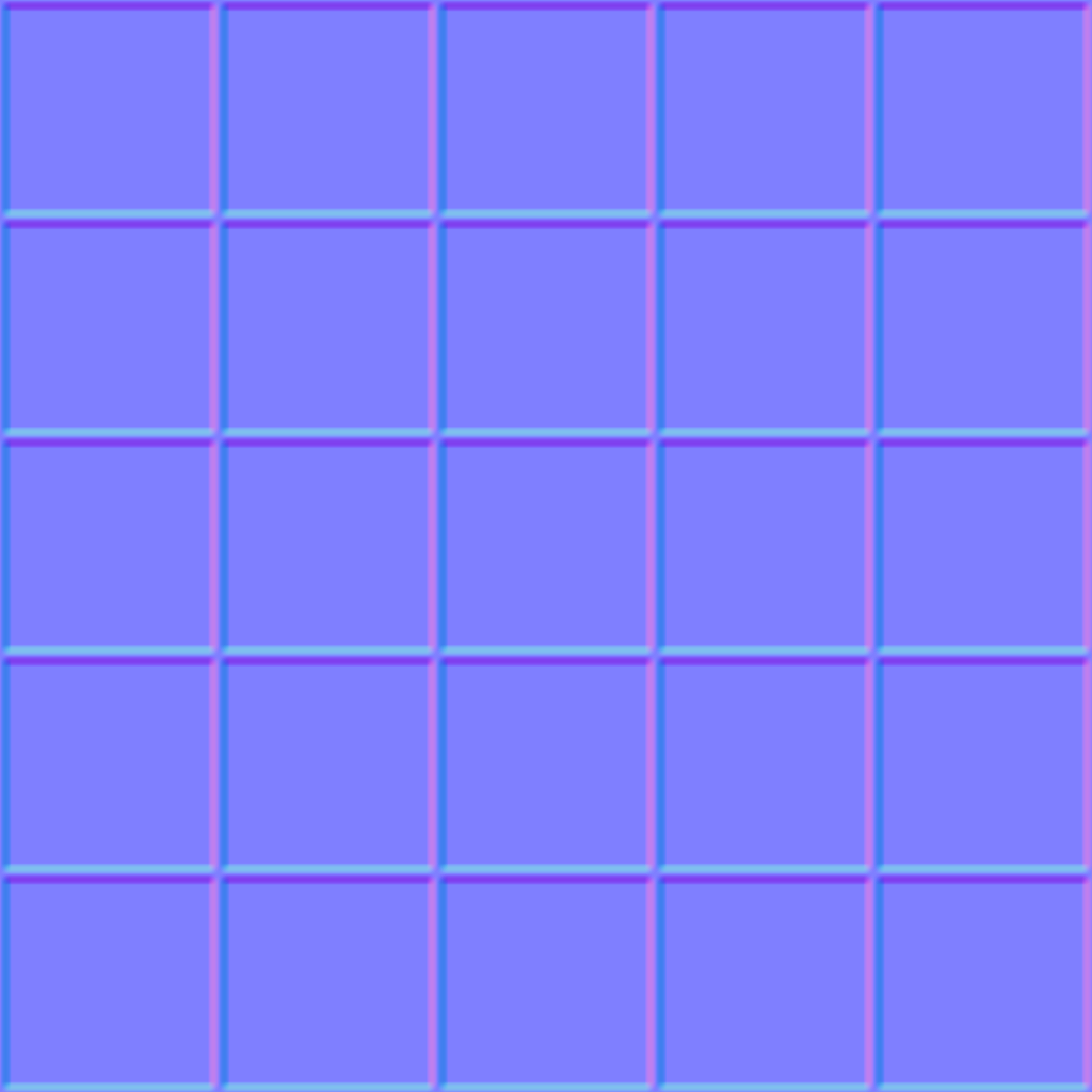
Just right-click and Save As. Drag these images into the content browser in the main Unreal window to add them as assets. Then drag those assets onto the material node editor to add them as TextureSample nodes. Connect them to the Base Color and Normal inputs like so:
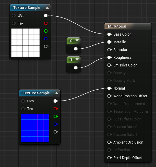
The TextureSample node has a whopping 5 color-coded outputs. The top one is a Vector3 containing the color of the texture. This is the one you’ll use most often. The red, green, and blue outputs below are the respective single color components of the image. The last, grey output is the “alpha channel” for the texture, if there is one. This is usually used for transparency in normal images, but for use in a game engine, this could be used for anything. Sometimes albedo maps will use the alpha channel for roughness information.
After hooking up this node, you’ll notice the material now has a base color pattern matching the mask texture, and the normal map added a subtle bit of depth to the cracks.
On the left side of the TextureSample nodes are two inputs: UVs and Tex. Tex is an input for a texture object – basically just another way to specify what texture to use. The UVs input is where you can specify the UV coordinates to sample the image at.
The way UV coordinates works is, the 3D model has coordinates for each vertex of each face. These coordinates map to a location on the texture so it can be displayed properly on the model. For example, this cube’s top face has four vertices – each corner. In this case, the UV coordinates for these vertices just map to the four corners of the texture, so the texture is streteched perfectly across the surface.
Now, we can fiddle with these coordinates to achieve certain results. By default, when the UVs input is unconnected, it’s hooked up to the model’s first UV channel automatically. (Models can have multiple sets of UVs for more complex materials.) Let’s manually add a TextureCoordinate node. The shortcut for this is to hold U and click. Hook it up to both UVs inputs.
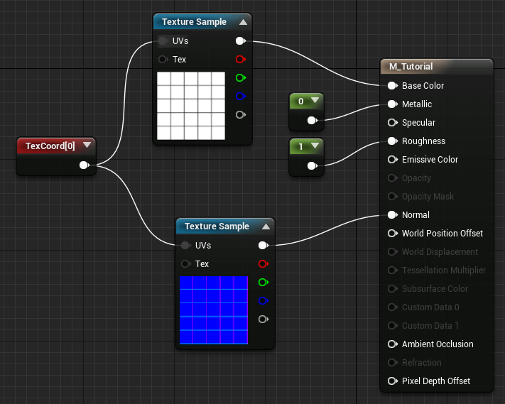
This setup is the same as not hooking up anything – the textures are using the model’s first set of UV coordinates. Now, let’s do some math! Add a Multiply node.
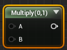
This node does exactly what you think. It has two inputs and one output – the output is the two inputs multiplied together. Add a constant node, and hook the TexCoord node and the constant to the inputs of the multiply node, and the output to the UVs of the textures.
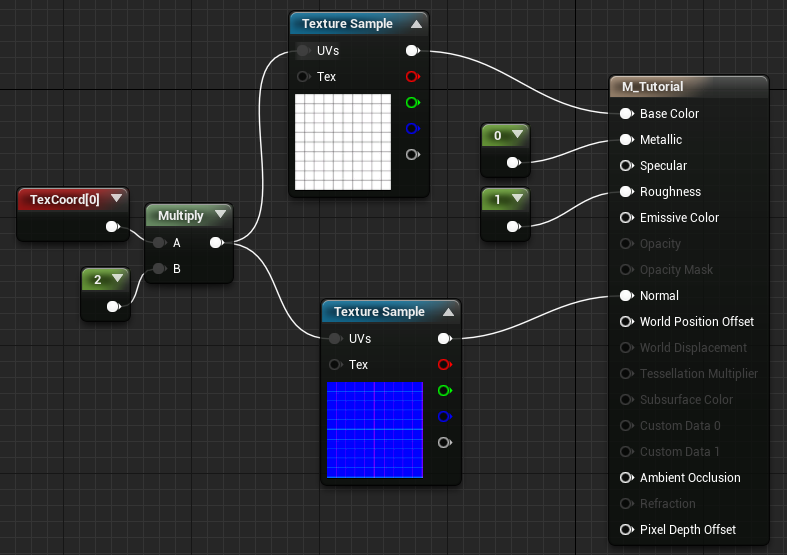
Now the model’s UV coordinates will be multiplied by the value of the constant. If you set it to 2, now the texture shrinks on the model, and is displayed tiled, 2x2. The reason for this is that the original upper-left corner of the model had a UV coordinate of (1,1), meaning the upper-left corner of the texture. We’ve multiplied that value to (2,2), which is outside the bounds of the texture, but it just repeats forever, so we just get more texture. Here’s a visualization:
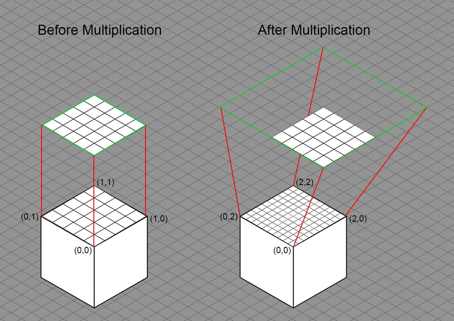
If you don’t totally understand what’s going on here, just think of multiplying the UVs as scaling the texture on the model.
Now, you can do math with any of these nodes, not just the UVs. Let’s add some color. Make another Constant3Vector node and multiply the output of the mask texture with it, routing the output of the multiply to Base Color.
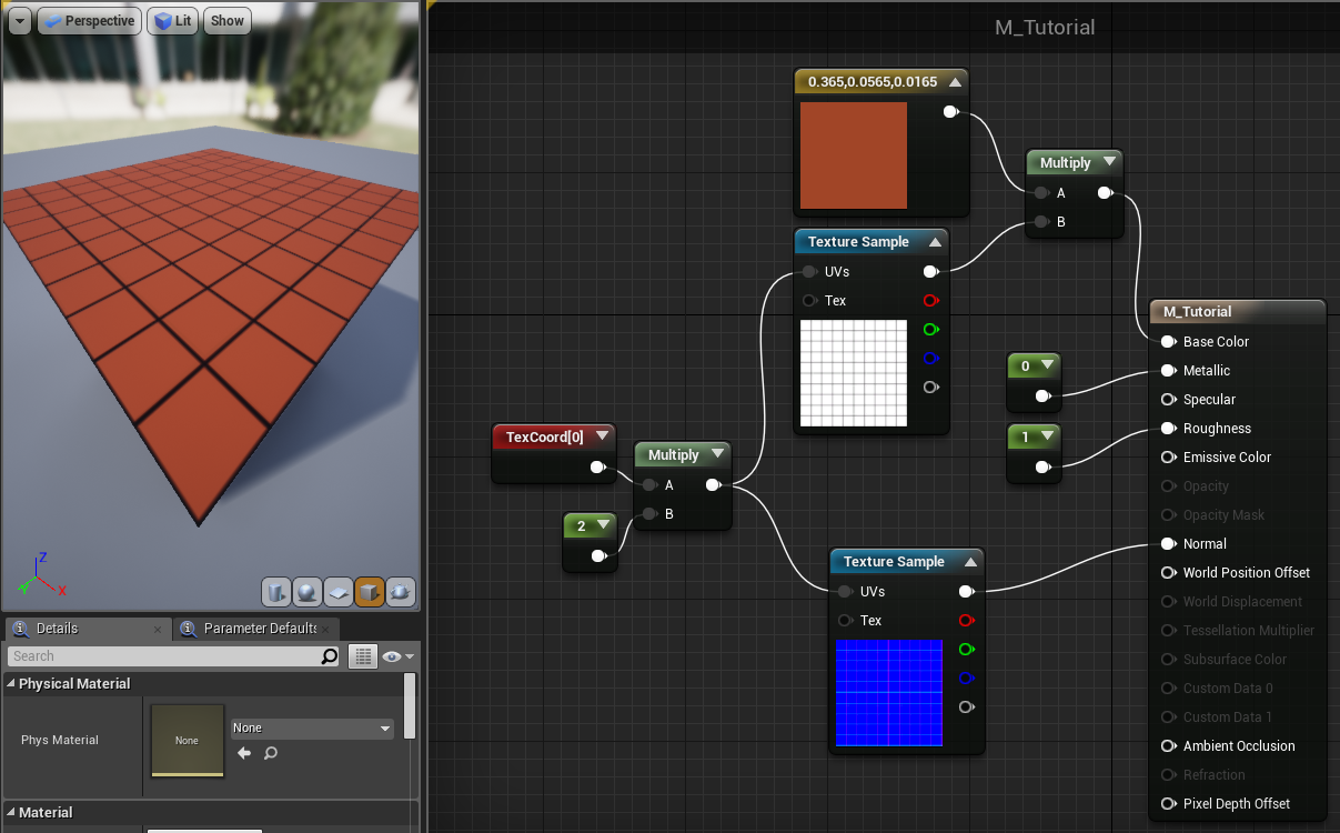
Since all these colors are just values between 0 and 1, we can do math with them quite easily! In this case, the mask texture is just white (1) in most places, with a black (0) grid. Multiply that by the provided color and, 1 × color = color and 0 × color = 0. Math!
Let’s add some noise. Add another TextureSample node (hold T and click). Select the node, and in the inspector, find the “Texture” value. Click on the dropdown to open a list of every texture available in this project.
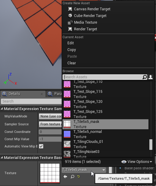
Unreal includes a few noise textures by default. You could select them from this list to use one. However, I don’t quite like how they look for this case, so I made my own noise texture:

Again, right-click and Save As and add it to the project. This time, select the new TextureSample node, find the “Texture” parameter again, and find the new noise texture in the dropdown menu. Remember that you can type to filter the list.
Hook up our scaled UVs to this texture, and connect the output to the Roughness input, replacing the constant node we were using before.
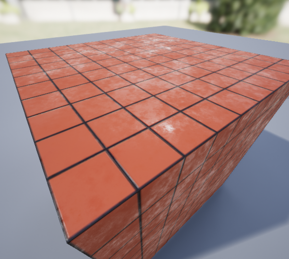
This adds an interesting, dirty, wet look to the tiles.
Now, I want to be able to tweak the intensity of this effect, but making changes in the material editor causes the material to recompile every time, which takes some time to update. Now is a good time to cover a powerful feature of Unreal Engine: Material Instances.
This is not only a standalone material, it can also be used as a template for multiple different materials, with tweakable parameters! Let’s add a parameter. Right-click on the constant attached to the UV multiplier and choose Convert to Parameter.
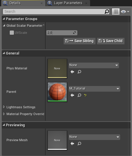
This makes the constant into a parameter for material instances. It’s still constant for the whole material, but we can set it for each instance. Here’s the inspector for the node:
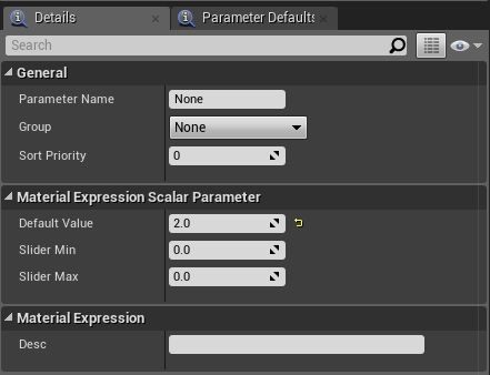
Name the parameter “UVScale”. The exact name isn’t important, it’s just the name we’ll see in the material instance editor. Group and Sort Priority can be used to group the parameters and control their order. Below that are the default, minimum, and maximum values. Set the minumum to 0.1 and the maximum to 10. We’ll see what this means in a moment.
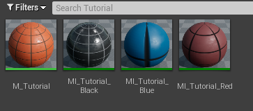
Save the material and return to the main Unreal window. Right-click on the material asset and choose “Create Material Instance”.
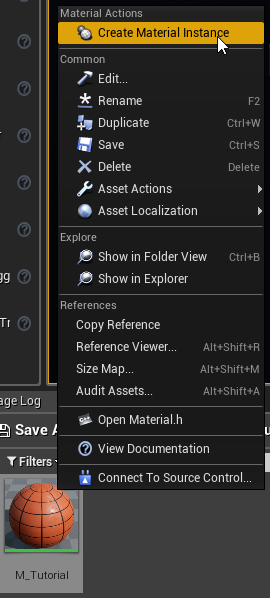
This creates an instance of this material. It’s basically the same underlying material, but we can alter any parameters we’ve made. Double-click on the material instance to open it.
The material instance editor is quite simple. It’s just a list of parameters on the left, and a huge preview window to the right. You can also select the preview model in the bottom-right corner here as well.
As you can see, our parameter UVScale is here! It’s disabled by default, so it uses the default value from the base material. Click the checkbox to override the default value, and drag the slider to change the UV scale. As you can see, the change is instant now, instead of having to wait for the material to recompile! Also you can see what “Slider Min” and “Slider Max” from before meant. Single constant parameters have a slider that you can use to quickly change the value. Note that the minimum and maximum values aren’t enforced, that’s just the range of the slider. You can click on the slider and type in any value you want.
Let’s go back to our base material and add some more parameters. In the inspector for the material instance editor, you can see the “parent” material. Just double-click on the thumbnail to open the parent material again.
Right-click on the Vector3 parameter for the Base Color, and convert it to a parameter too. Call it “TileColor”. Note that Vector3 parameters don’t have options for a slider, since they won’t have a single slider in the material instance editor.
Now, copy and paste that parameter node, and name the copy “GroutColor”. Now, make a new node, either by right-clicking or using the side menu. The node is called “LinearInterpolate”.
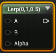
Linear interpolation is just a way of blending between two values. You provide two inputs, A and B, and the Alpha value controls where between the two you want the output to be. “Interpolate” means to blend between two values according to some function, and “Linear” just means the Alpha maps linearly to the blending, as opposed to exponentially or by some other function. So if Alpha is 0, the output is completely the A, if it’s 1 the output is completely B, and if it’s 0.5, it’s an even mix of the two. Any other value will be somewhere between the two.
In this case, we’ll be using the mask texture as our Alpha, to interpolate between our tile and grout colors. Hook up the GroutColor node to A, the TileColor to B, and the mask texture to Alpha. Hook the output up to Base Color. Delete the old multiply node we were using there.
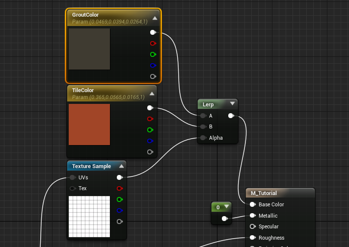
Now, where the mask texture is 1 (white), the base color will be B, which is TileColor, where the mask is 0 (black), it’ll be A, our GroutColor. And it will fade smoothly in between according to the mask.
Save the material and return to the instance we made before. Our two new parameters show up now, and we can change the tile and grout color in here with immediate feedback.
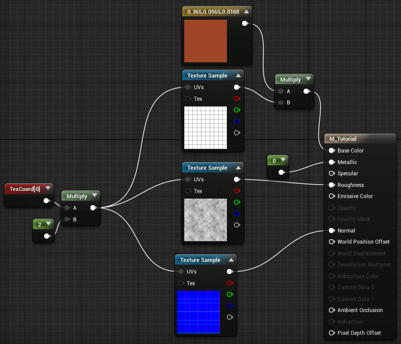
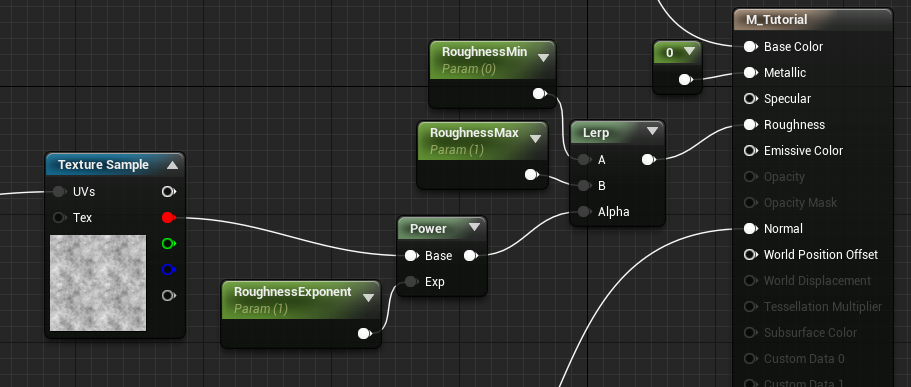
Oops, I’m just now remembering that the reason I explained parameters and instances was to tweak the Roughness. Let’s do that now. Add these nodes and hook them up as follows:
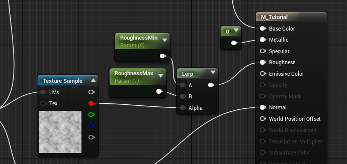
(That’s two constant parameters hooked up to a lerp, with the noise texture as the Alpha). Note that I’m using the red channel of the noise texture. The Alpha input to the lerp node must be a “scalar value”, which is another way of saying a single numeric value. Colors are Vector3s, which are 3 numbers in one, so we can’t route that into Alpha. Instead, we just grab one of the channels – since the texture is black and white, all the channels are the same, so I just picked red.
Now, the noise texture will blend the roughness between the values supplied by the parameters. If we set them to 0.5 and 0.75, then where the texture is black would be roughness 0.5, white would be 0.75, and the greys would be values in between. Functionally, we’re remapping the noise texture from (0,1) to (min,max). Now we can tweak the effect more carefully. I’ll also add a parameter to exponentiate the mask value:
Since colors are just numbers, we can do any kind of math with them, including exponentiation (powers/roots)! Here’s what the noise texture looks like when squared and square-rooted:
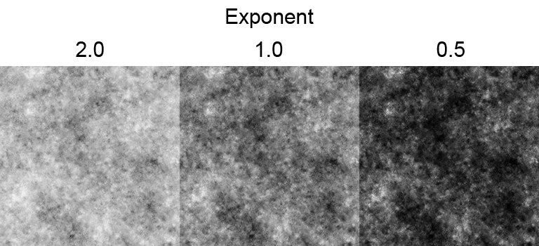
Head back to the material instance and tweak the exponent. Hopefully it should be easier to understand when you see it demonstrated.
We’re almost done with this one! If you look closely, you can see that the noise texture is affecting the roughness inside the grout, whereas I want the grout to always be rough. The fix is fairly easy, just multiply the roughness by the mask texture, right? Well, the mask texture is actually backwards from what we want. This would make the grout roughness 0, when we want roughness 1. But we can’t just invert it and multiply, because that would make everything else zero.
What we’ll do is invert the texture so the grout lines are white, then add it to the roughness. This will result in some roughness values greater than 1, which shouldn’t be a problem since Unreal clamps roughness automatically, but we’ll add a clamp node just to be safe, which clips the values to keep them inside a specified range.
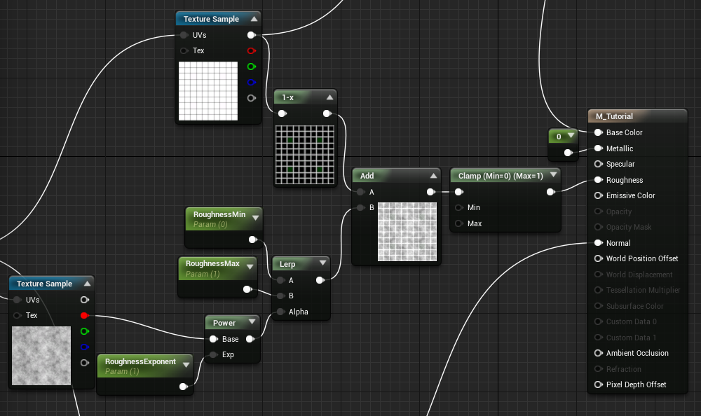
The invert node is called “OneMinus”, since it just performs 1-x on the input. This is different from multiplying by -1, but for values between 0 and 1, the result is the same. Notice that I expanded the OneMinus and Add nodes by clicking on the triangle. This is one instance where the visualizations are helpful. The clamp node is just called “Clamp”, and the default values for the extents are 0 and 1, which is exactly what we want.
Whew! That’s pretty complicated. When the node graphs start getting big, you can use reroute nodes to keep things tidy. These are just points you can use to control where the connecting lines go. To add a reroute node, double click an existing line, or right click and select Add Reroute Node (type to filter). You can also drag a line out from a node and release to open the menu, then start typing to add any node, including reroute nodes.
Here’s our final graph:
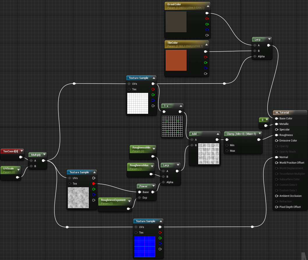
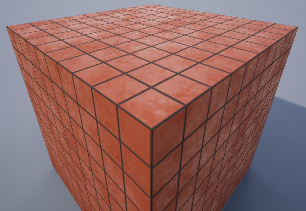
Try making several instances and tweaking the values to make different tiles!