This is the first in a series of posts explaining how 3D rendering works. These posts are designed to help new game developers understand the terminology, as well as the underlying concepts, as quickly as possible. They are designed for readers that plan on using a game engine (like Unity or Unreal Engine) that deal with the nitty-gritty stuff for them. You won’t find complex matrix transformations or raytracer implementations here. You’ll have plenty of time to read about all that on your own if you’re interested. For now, we’ll get started with the basics.
If you’ve dabbled in game dev at all, you’ve probably heard of something called a “shader”. This is a piece of code that was written to run on your video card, in order to draw graphics on a screen. A simple shader might look like this:
#version 410 layout (std140) uniform Matrices { mat4 projModelViewMatrix; mat3 normalMatrix; }; in vec3 position; in vec3 normal; in vec2 texCoord; out VertexData { vec2 texCoord; vec3 normal; } VertexOut; void main() { VertexOut.texCoord = texCoord; VertexOut.normal = normalize(normalMatrix * normal); gl_Position = projModelViewMatrix * vec4(position, 1.0); } If you don’t understand any of that, don’t worry! Enough tools exist that you probably won’t ever need to write shader code like this, at least not until you already know what you’re doing.
Now, I’m going to stop talking about “shaders”, because most modern tools abstract these shaders away into “materials”. Instead of reasonaing about rendering in terms of programs, like a computer might, a material describes the physical properties of a thing you’re rendering. What color is it, how does it reflect light, how opaque is it, etc. A single material may be made up of many shaders under the hood, but we’ll let the tooling deal with that.
I will specifically be covering the Metallic/Rougness PBR workflow. This is the workflow used by Unreal Engine (my engine of choice). There is also the Specular/Roughness workflow, which is an alternative way of modelling materials. Here's an article explaining the difference: https://www.marmoset.co/posts/pbr-texture-conversion/#metalvspec
Physical properties
Here we’ll define the various physical properties that make up a material definition.
Albedo (or Diffuse Color)
This one is pretty straightforward, it’s the basic surface color of the material.
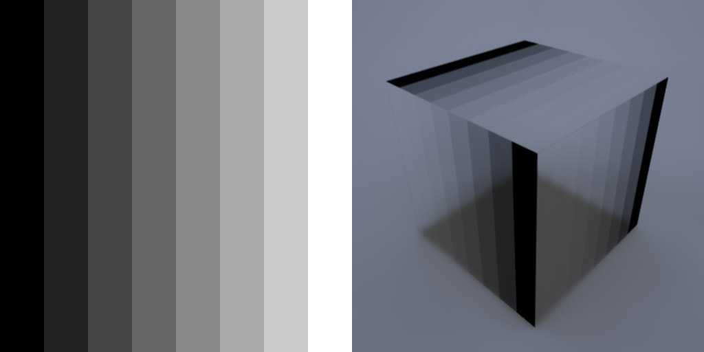
Roughness
A value between 0 and 1 that describes how “shiny” a material is. At high values, the material is “rough” and so most light is absorbed or scattered and little is reflected. At low values, the material is “smooth” and reflects most light.
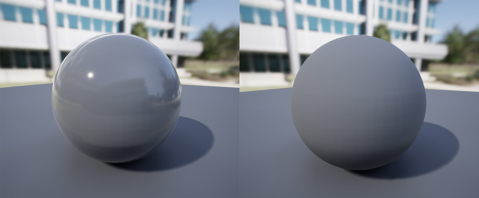
Left: roughness 0.1Right: roughness 0.9
Metallicity
This one is tricky. The reflected color of a metal is defined by the angle between the viewer and the light source. Unlike “specular highlights” that show up as a bright spot like on the low-roughness example above, the brightness of metallic sheen is based on the viewing angle.
Basically, metals reflect light differently from non-metals. The “metallic” value controls how “metal-like” a material is, where 0 is regular, non-metal reflections, and 1 is fully metallic reflective behavior.
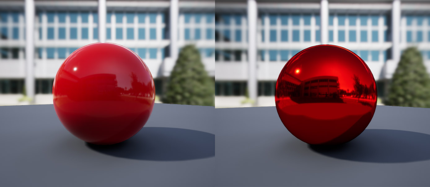
Here’s a comparison of two white materials, with roughness 0, one with metallic 0 and one with metallic 1.
Left: metallic 0Right: metallic 1
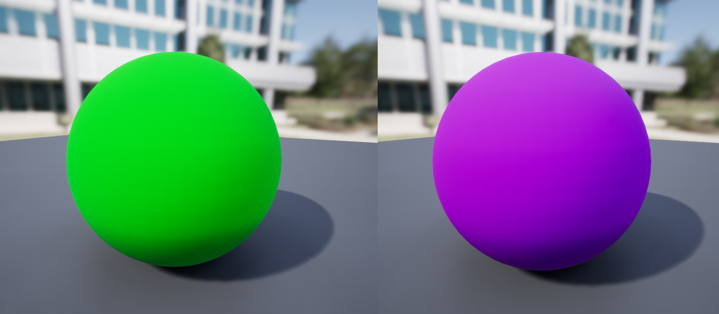
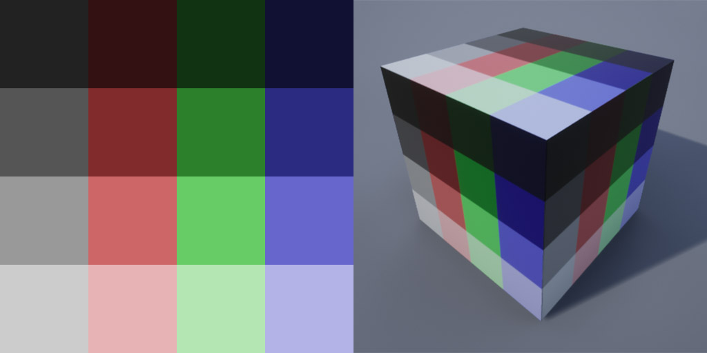
Here’s a comparison with a red albedo value instead.
Left: metallic 0Right: metallic 1
Opacity
Opacity describes how transparent a material is. At 0, the material is fully transparent, and therefore invisible. At 0.5, it’s half-transparent and see-through. At 1 it is fully opaque and cannot be seen through at all.
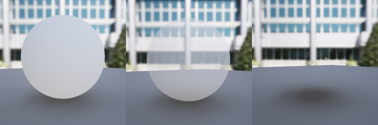
Left: opacity 1Center: opacity 0.5Right: opacity 0
Emissive
The emissive value controls how much light a material emits. By default, this is zero, since most materials don’t glow. However, you can set this value to greater than zero to make a material emit light. (Note that this light often won’t be cast onto other objects in a game engine, as calculating bounce light from emmisive materials is very computationally expensive.)
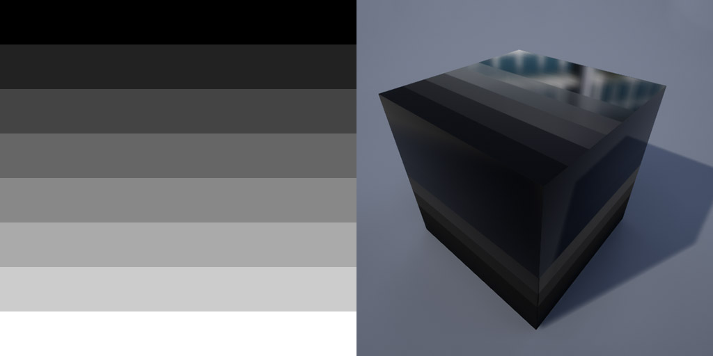
Here are a few black materials with various emissive values. On the left is no emissive value, on the middle is fully red, and on the right is a value of red greater than 1. This may do nothing depending on the engine you’re using, but many support emissive values greater than 1, which just means they emit more light.
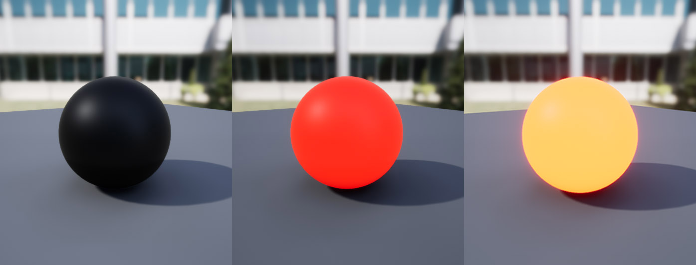
Left: emissive 0Center: emissive red (1,0,0)Right: emissive red (10,0,0)
Notice how the middle one is bright, but not really brighter than if it were just red. Keep in mind its albedo color is black. The one on the right, by contrast, is glowing brightly, with light bleeding around the edges due to bloom. Notice however, that the light isn’t being cast onto the floor as if it were a point light.
Subsurface Color
This parameter controls the colors scattered by a phenonenon known as “subsurface scattering”. Some materials, like human skin, scatter light inside the substance. This can be seen by shining a light through your hand. The light will spread out through the skin under the surface. You’ll notice that even if you shine a white light, the light scattered is always red. This is because skin absorbs most frequencies of light, but scatters red light beneath the surface.
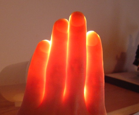
Image from Pluralsight.com (no longer on original article).
The “subsurface color” parameter affects the color of light that is scattered beneath the surface of the material. The example on the left below has no subsurface color, meaning no light is scattered beneath the surface. The material on the right has a red subsurface color, so red light is scattered.
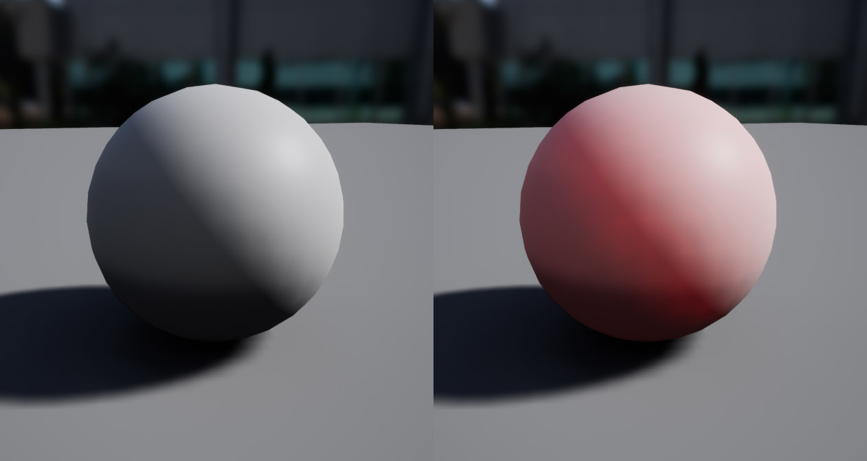
Left: subsurface color black (no color)Right: subsurface color red (1,0,0)
Specular
In a Metallic/Roughness PBR workflow, the specular value is not used for metals. In non-metals, it can be used to tweak the reflectivity of a material. In Unreal Engine, it is 0.5 by default. which works for most solid materials. If the specular value is ever used, it’s usually set by a texture map, which I’ll explain below.
Normal and Ambient Occlusion
These don’t make much sense as a single value, so I’ll explain it below, once we cover texture maps.
Texture Maps
Here’s where things get interesting! Instead of using a single value to describe an entire material, we can use special “textures”, which are images describing the various values for a certain property. “Texture” is just the name for an image when it’s used in rendering software. When referring to textures that control parameters in a shader or material, they are usually called “maps”, e.g. “albedo map”.
Albedo
Here’s an example of an material with an “albedo map”. On the left is the texture used, and the resulting material is on the right.
As you can see, the object has different albedo values across its surface, as defined by the albedo map.
Roughness
Roughness maps are used to describe how an object’s roughness changes across its surface. Think “shiny in some places and not in others”.
Opacity
Rendering transparency is gernerally pretty computationally expensive (since you have to render both the object itself and whatever is behind it), so most rendering engines don’t by default; they assume most objects are opaque. If you want to render an object to be see-through, there are two different ways to do it: translucency and opacity masks.
Translucency is the “normal” way to render transparency:
It’s best to avoid this kind of transparency unless it’s necessary for a certain effect, as it is expensive to render.
The other kind of “transparency” is with opacity masking, or “cutout transparency”. In this mode, you supply a “mask” texture that defines what parts of the material to draw:
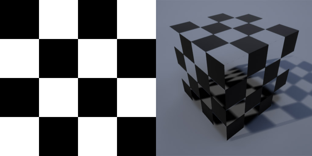
Note that in this mode the material can only be fully opaque or completely invisible, nothing in between. This is so that the renderer never has to draw both the foreground and the background on top of each other, like with partial transparency. It’s useful for things like leaves on a tree, where you can supply the shape of the leaf as an opacity mask and just draw a single rectangle with the shape of the leaf masked out.
Metallicity and Subsurface
Metallicity and subsurface color are usually constant for a certain material. One exception might be if you used one material to render an object with multiple different surface types, but doing so sort of goes against the whole concept of materials. Occasionally using a metallic map can make objects look more realistic, especially things like rocks that actually have varied metallicity in real life.
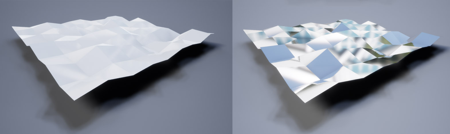
Normal
Okay, this one is really cool. Normal mapping is a technique used to “cheat” extra surface detail into an object, without increasing the number of polygons in a model. Basically, you create a “normal map” that describes the slopes along a surface, and the renderer adds some shadows in certain places to fake depth. The map describes what’s known as a “normal”, which is a vector describing the direction of a face. In simple terms, the red channel describes different surface angles along one axis, and the green channel along the other axis. The blue channel is usually ignored, since we’re only describing a surface in two dimensions.
Here’s an example from wikipedia (courtesy of Julian Herzog):
On the left is a 3D model with actual shapes in the model itself. In the middle is a normal map representing the surface angles, or normals, of that model. On the right is a flat plane, rendered using that normal map. As you can see, even though it’s just a single flat plane, the shading creates the illusion of extra depth. For shallow details, this works just fine and can help recreate fine details while still maintaining a low polygon count on the actual model.
Ambient occlusion
Ambient occlusion is a rendering technique that mimics the way light gets trapped inside narrow spaces. Here’s a real-life example:
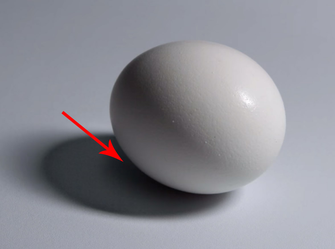
Image from proko.com.
In the tight space between the egg and the table, light gets trapped, so there’s a darker shadow there. General ambient occlusion is handled automatically be the lighting engine, but you can provide an AO map that describes places on the material that you want to manually add extra shading. This is similar to a normal map except it’s one-dimensional – it just describes the shading.
Here’s an example of an AO map used to add shading detail to a face:
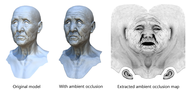
Image from Autodesk.
Specular
A specular map is sometimes used with non-metals to change the specific reflectivity of a material. I won’t cover specular maps right now because it’s a more advanced topic, and generally unnecessary in a Metallic/Roughness PBR workflow. I may cover later it in an advanced rendering article.
Material Examples
Now I’ll cover a few example materials, so you can see how all the pieces fit together.
Wood floor
Here’s an example of a wood floor material, adding one map at a time to show how each one affects the surface.
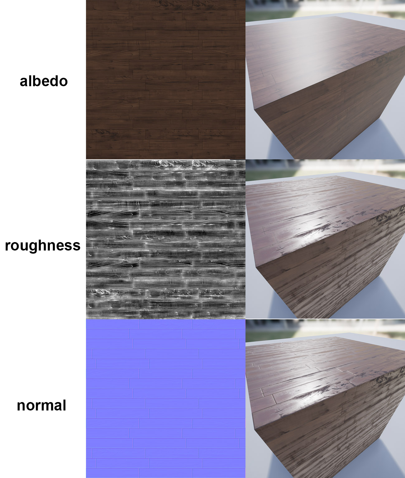
The albedo map adds the color of the wood, but it still looks unnatural without detail. The roughness map adds areas that are smooth or rough, which immedately improves the look. Finally, the normal map adds the cracks between boards and small surface details.
Cobblestone
This one includes a metallic map, which is fairly rare. In this case it’s because the rocks are partially metallic, so varying the metallic value makes them look more realistic.
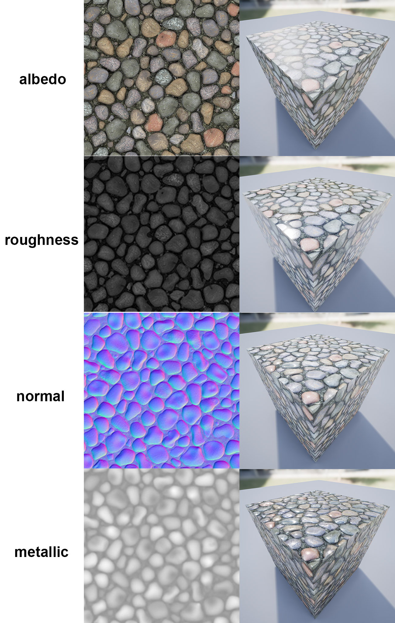
The details in this one are pretty subtle, but pay attention to how the metallic map makes the rocks look a bit more metallic and shiny, while keeping the dirt between them dull.
Leaf
Here’s an example of a leaf material that uses opacity masking.
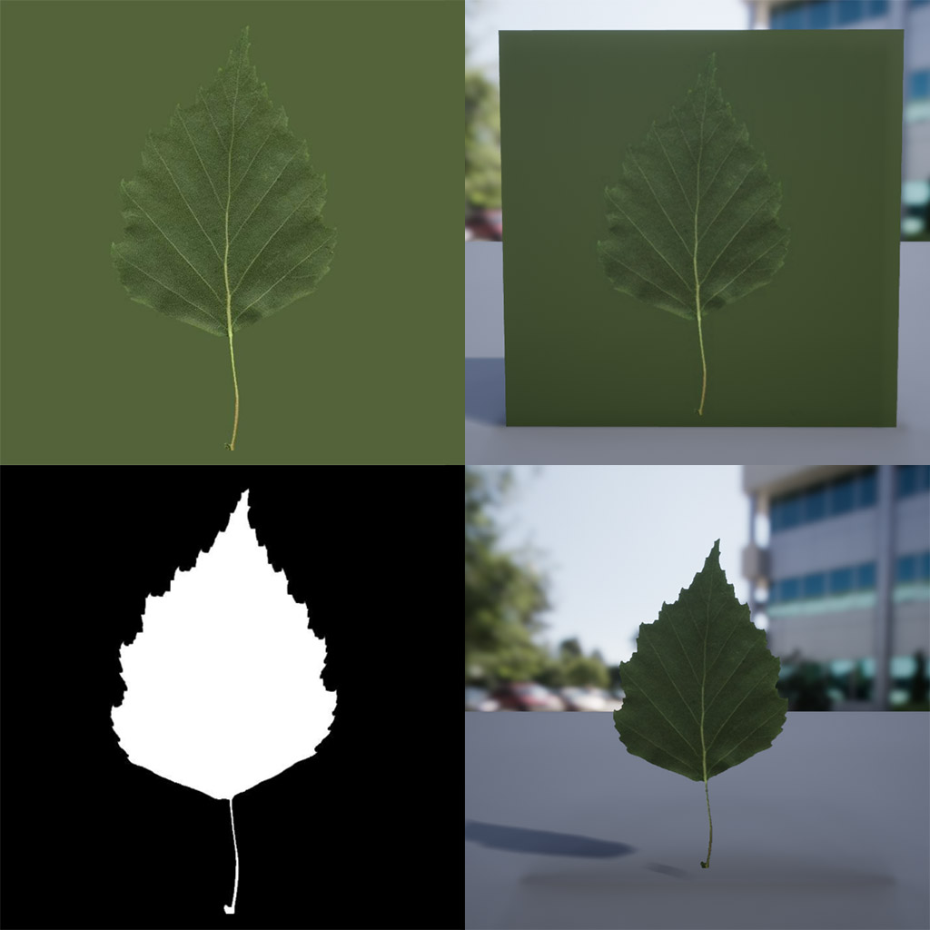
On the left side are the albedo map (top) and the opacity mask (bottom). On the right is the material rendered without the mask (top) and with the mask (bottom). Using masked opacity as opposed to full translucency is especially important for leaves since you usually render hundreds of them at once. The added cost of full translucency would add up quickly.
Wrapping Up
Whew! Hopefully that helps explain how material-based rendering works. I’ll probably be writing more posts soon, including a tutorial for Unreal Engine’s material editor, so you can make your own materials. If there’s something here you don’t understand, please email me at hello@trashbyte.io or message me on cybre.space (@trashbyte)! I wanna make sure these guides are easy to understand, and I’m happy to make edits to make them clearer.